
This article discusses many of the factors associated with segmental concrete bridges in the hope that designers may be better informed when selecting structure types for their next bridge.
We are seeing an increasing number of concrete bridge designs come to fruition, especially in the U.S., and they have been mainly in the form of segmental concrete construction. The versatility of segmental construction enables construction materials and/or complete precast units be delivered to their service location quite invisibly. The contractor’s gantries, formwork and special equipment can be set up with ground cranes at strategic locations and times (such as at night or on weekends) to minimize disruption to the environment or the public. Once the special equipment and gantries are in place, work can progress uninterrupted. Segments or materials can be stockpiled on the approach roads and/or partially completed portion of the structure in order to reduce the need for staging areas immediately adjacent to construction sites.
We are seeing an increasing number of concrete bridge designs come to fruition, especially in the U.S., and they have been mainly in the form of segmental concrete construction. The versatility of segmental construction enables construction materials and/or complete precast units be delivered to their service location quite invisibly. The contractor’s gantries, formwork and special equipment can be set up with ground cranes at strategic locations and times (such as at night or on weekends) to minimize disruption to the environment or the public. Once the special equipment and gantries are in place, work can progress uninterrupted. Segments or materials can be stockpiled on the approach roads and/or partially completed portion of the structure in order to reduce the need for staging areas immediately adjacent to construction sites.
It is important that designers understand some of the basics affecting segmental bridge design and construction in order to made decisions about whether or not a segmental bridge is the most appropriate type for any given project. Bridge projects considered appropriate for a segmental design usually meet one or more of the following conditions:
- They are large and there is the potential for a lot of repetitiveness in construction details.
- They are complex because:
– Access to the sites poses significant challenges
– Traffic disruption around the sites must be kept to a minimum. - Aesthetics are considered a significant aspect of the designs.
Segmental Construction Techniques
Segmental concrete bridges come in many forms, but are generally categorized by how they are built. The main construction techniques used for segmental bridges are span-by-span, cantilever, and incremental launching.
Span-by-Span Construction. In span-by-span construction, the bulk of the dead load in each span is applied initially to the structure by a positive moment at or near the midspan. Consequently, the post-tensioning tendons that hold the spans up tend to be heavy about the midspan and placed low in the bridge cross-section (Figure 1). The variations that have seen successful include having the spans:
- Precast into short segments of approximately 3-m (10-foot) lengths for ease in handling
- Built in horizontal lifts on rolling forms or special travelers
- Cast off-site and hoisted in complete span-units.
 |
| Figure 1: Continuous Span-By-span Design Moment and Tendon Schematic |
The precast option is by far the most popular of these variations because of its rapid rate of construction. Once the crew has learned the routine, it is not unusual to consistently get two to three spans erected in a week. Figures 2 through 4 show several variations of the span-by-span construction method.
 |
| Figure 2: Precast Segments Erected by Ground Crane |

 |
| Figure 4: Horizontally Segmented Construction |
Cantilever Construction. This method is quite opposite to the span-by-span method in that it has the majority of the dead load introduced into the structure as cantilevers over pier supports. As a result, the final structures see significant negative moment over the piers, and the post-tensioning tendons in the superstructure tend to be heavy about the pier supports and placed high in the bridge cross-section (Figure 5).
 |
| Figure 5: Cantilever Construction Moments and Tendon Schematic |
Cantilever construction has seen a large variation of successful applications, the majority of which have segments in the range of 3-m to 4.5-m (10-foot to 15-foot) lengths depending on whether the segments are precast or cast-in-place. There are also cases where an entire cantilever is cast off site, delivered and then lifted into final position. Figures 6 and 7 illustrate several applications of the cantilever method of construction.
 |
| Figure 6: Cast-in-Place Balanced Cantilever with Form Travelers |
 |
| Figure 7: Precast Segment Erected by Overhead Gantry |
Incremental Launching. The bridge cross-section is typically constructed at an abutment and pushed into its final position. This method causes each bridge section to experience a wide range of positive and negative moments inherent to the span layout before coming to its final position. The maximum negative moment occurs just prior to touching down at the next pier. A steel launching nose is often used to reduce the demand imposed by the launching stages so that construction does not govern the choice of the cross-section and principal aspects of the design. The length of the launching nose is generally about 65 percent of the longest span (Figure 8).
 |
| Figure 8: Incremental Launching of Girder With a Steel Nose |
Another method that has been used involves a system of temporary stay cables and a tower mounted at the front part of the superstructure to lift the tip of the superstructure, thus reducing the negative moment. Temporary post-tensioning tendons are designed to be nearly concentric to the centroidal axis of the bridge cross-section to provide appropriate compression in both the top and bottom fibers of the cross-section. This method requires that the underside (soffit) of the superstructure follows a constant profile and curvature. Several projects that have complex roadway geometries were accommodated by varying the height of the girder webs and the overhangs of the roadway slabs.
Design Considerations
Stress History and Its Influence on Design. Like many other structure types that are constructed in stages (e.g., composite steel construction), a segmental bridge must be designed to account for the construction stress history. The design process for segmental bridges must also address creep and shrinkage that may be significant during construction and after construction is completed. This means that the design computation must account for the sequence as well as the schedule of construction. Fortunately, these physical phenomena and their effects on design are well documented. Also, a host of commercial computer programs are available to track the stresses and displacement history of a constantly evolving segmental bridge. Good engineering practices have also been progressively codified over the years to ensure uniformity in the design products.
- Horizontal and vertical clearances
- Geometry of the alignmentrequired by the crossing
- Construction schedule
- Site constraints, such as access
- Environmental requirements
- Visual impacts
- Aesthetics
- Economical span range
- Span to depth ratios.
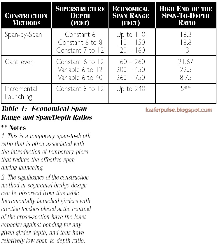 |
| Table 1: Economical Span Range and Span/Depth Ratios |
Choosing the Method of Construction
Perhaps more so than other bridge types, the segmental concrete bridge manifests the inter-relationship of design and construction knowledge. Given the impact of construction methods and construction loads on the basic design of a segmental bridge, a design for service load alone is inappropriate. An engineer must evaluate the project as a whole before deciding on the method of construction, span arrangement, static scheme and cross section to be used. For this same reason, a feasible, cost effective and complete construction sequence and methodology should be presented in the design drawings. Where viable, the construction contract should make allowance for the contractor’s proposed modifications with regard to construction technology. Provisions should be provided in the specifications with the basic system requirements presented clearly to facilitate accurate and responsive bidding.
Perhaps more so than other bridge types, the segmental concrete bridge manifests the inter-relationship of design and construction knowledge. Given the impact of construction methods and construction loads on the basic design of a segmental bridge, a design for service load alone is inappropriate. An engineer must evaluate the project as a whole before deciding on the method of construction, span arrangement, static scheme and cross section to be used. For this same reason, a feasible, cost effective and complete construction sequence and methodology should be presented in the design drawings. Where viable, the construction contract should make allowance for the contractor’s proposed modifications with regard to construction technology. Provisions should be provided in the specifications with the basic system requirements presented clearly to facilitate accurate and responsive bidding.
Conclusion
As never before, segmental technology has matured to a point where its acceptance is widespread. Concrete technology has also made recent advancements that will further bolster the viability of segmental designs.ftnt1 Designers should be aware of the benefits that this type of construction has to offer to a project and give it due considerations. The results may be a competitive design that is relatively low in maintenance and aesthetically pleasing.
No comments:
Post a Comment